Starting point
Figure 84 presents the main window for defining Backfills. The modeling of the upstream fill is identical to that of the downstream backfill. Only the modeling of the downstream backfill is presented here.
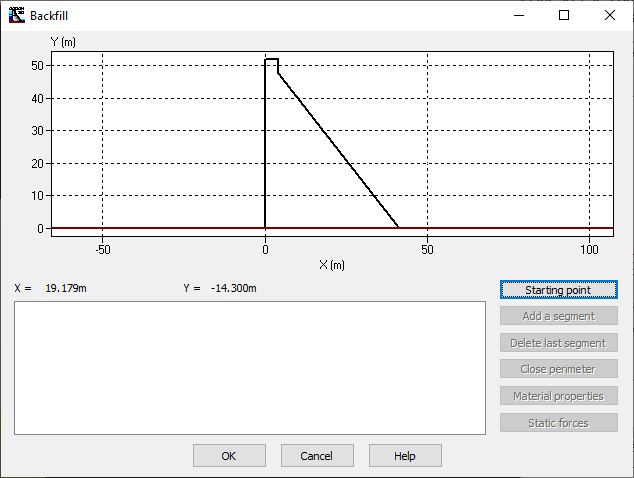
Figure 84
To define the downstream backfill, the user must first determine the contact point between the crest of the backfill and the gravity dam. For that, the user must click the Starting point button to access the Downstream face starting point window, shown in Figure 85. The authorized locations for the starting point are indicated with the red lines. The user can then set the X position or the Y elevation and then let the software calculate the corresponding position or elevation. The user can also determine the coordinate bypassing the software. The software validation of the starting point coordinate indicates that the user can continue the definition of the fill. Otherwise, the user must check the coordinate of the starting point so that it coincides with the red lines.
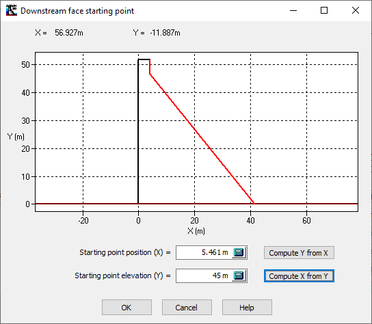
Figure 85
Figure 86 shows the position of the starting point previously defined by the user. At this point, it is possible to build the outer perimeter of the backfill using the construction tool by segment.
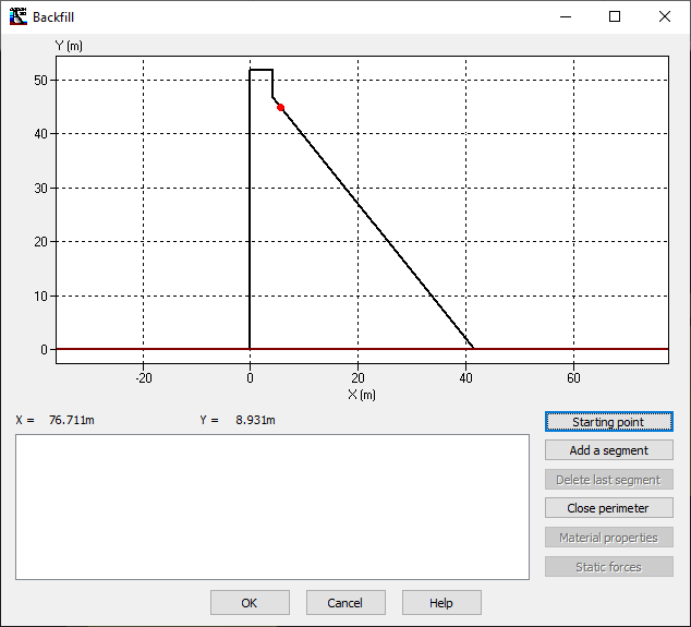
Figure 86