Spillway
File: V3-E1.dam
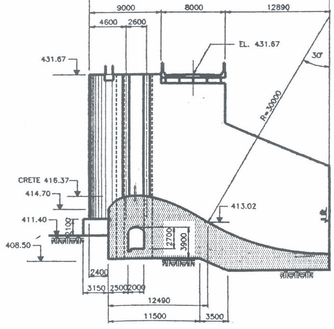
An elevation view of the spillway is shown in Figure 185
Currently, no software, similar to CADAM3D, is available for comparison. The results of two independent calculations are used here:
- Independent manual calculation (MS Excel)
- Manual calculation (Hydro-Québec)
Six load combinations are considered:
N1: Dead load, hydrostatic load, uplift pressure with drains, static ice load
N2: Dead load, hydrostatic load, uplift pressure with drains, dynamic ice load
E1: Case N1 with no drains
E2: Case N2 with no drains
E5: Case N1 with horizontal seismic load
E6: Case N1 with vertical seismic load
In the independent manual calculation, it is assumed that sliding can occur along an inclined plane (from the upstream to the downstream point of the foundation) and the uplift pressure is considered along this surface. Uplift was calculated along multiple planes at the base and then projected horizontally along this surface. The results of the two hand calculations are not identical since the assumptions are different. However, in practice, the results are close enough. The results of CADAM3D are in better agreement with the independent manual calculations. The small differences stem from simplifications made to assess the weight and loads in this complex structure.
Comparison of results at the base:
|
|
|
Loading combinations |
|||||
|
|
|
N1 (kPa) |
N2 (kPa) |
E1 (kPa) |
E2 (kPa) |
E5 (kPa) |
E6 (kPa) |
|
CADAM3D
|
U/S normal stress |
-117.8 |
-102.9 |
-27.3 |
-12.4 |
-80.7 |
-110.7 |
|
D/S normal stress |
-164.8 |
-179.3 |
-151.6 |
-166.1 |
-200.7 |
-164.3 |
|
|
Independent manual calculation |
U/S normal stress |
-117.8 |
-103.1 |
-26.9 |
-12.2 |
-71.9 |
-97.7 |
|
D/S normal stress |
-165.9 |
-180.3 |
-153.0 |
-167.3 |
-209.1 |
-163.0 |
|
|
Manual calculation (Hydro-Québec)
|
U/S normal stress |
-108.8 |
-93.7 |
-26.0 |
-10.9 |
-60.9 |
-89.4 |
|
D/S normal stress |
-183.1 |
-198.2 |
-171.6 |
-186.7 |
-231.0 |
-179.4 |
|