Performance criteria
For each load combination, Allowable Stresses are defined by applying factors to tensile and compressive strengths (Figure 169). The user can change these values. These values are not used in the software. Allowable stresses are presented in the output to facilitate the interpretation of safety factors or calculated stresses.
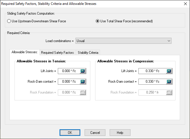
Figure 169
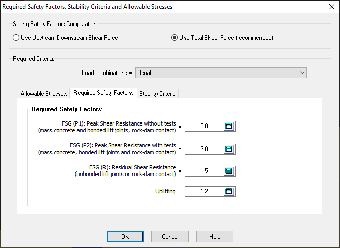
Figure 170
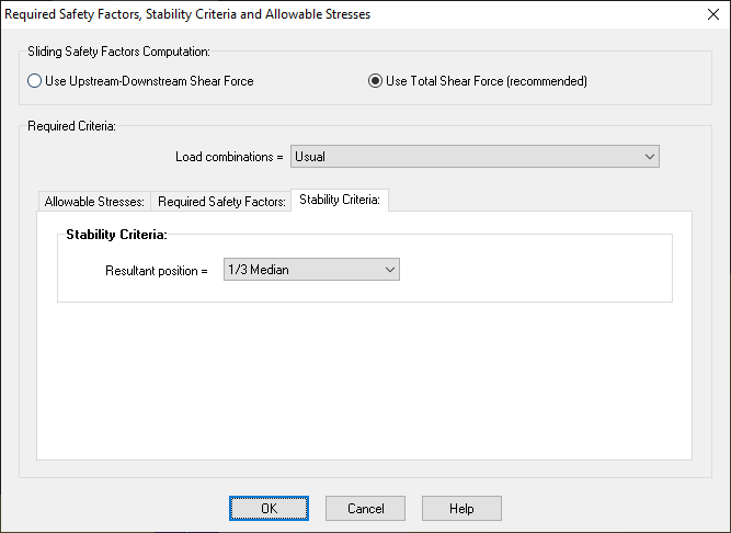
Figure 171
Default values in CADAM3D
|
Safety factors, stability criteria and allowable stresses |
|||||
|
Performance indicators |
Load combination |
||||
|
Normal |
Unusual |
Extreme |
|||
|
Ineffective drains or unusual ice |
Post-seismic |
Seismic |
Flood |
||
|
allowable stresses in tension |
|
|
|
|
|
|
0 |
0.025 f 'c |
0.033 f 'c |
0.075 f 'c |
0.05 f 'c |
|
0 |
0 |
0 |
0 |
0 |
|
allowable stresses in compression |
|
|
|
|
|
|
0.33 f 'c |
0.5 f 'c |
0.67 f 'c |
0.9 f 'c |
0.67 f 'c |
|
0.25 f 'c |
0.5 f 'c |
0.5 f 'c |
0.67 f 'c |
0.5 f 'c |
|
Resultant position |
1/3 median |
1/2 median |
In section |
In section |
In section |
|
Sliding Safety Factor |
|
|
|
|
|
|
3.0 |
2.0 |
2.0 |
1.3 |
1.3 |
|
2.0 |
1.5 |
1.5 |
1.1 |
1.1 |
|
1.5 |
1.3 |
1.1 |
1.0 |
1.0 |
|
Uplifting Safety Factor |
1.2 |
1.1 |
1.1 |
1.1 |
1.1 |