Lift joints (analysis planes)
After defining the mechanical properties of the lift joints, their positions must be specified using the Lift joints command. The rock-concrete interface is considered an existing joint (Base) by CADAM3D and is listed in the window shown in Figure 117.
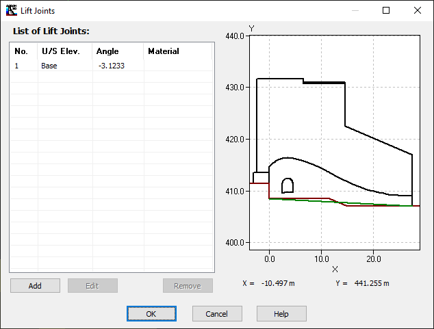
Figure 117
New lift joints can be generated using the Add command. The elevation, inclination angle and material type must be specified in the Lift joint creation window (Figure 118). This window also allows the automatic generation of lift joints over the height of the structure. The same inclination angle and material type are then assigned to the group of joints generated.
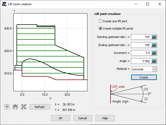
Figure 118
Once the joints (analysis planes) are created, CADAM3D allows viewing these planes. The user must select a joint from the list (see Figure 117) and then click the Edit button to obtain the window shown in Figure 119.
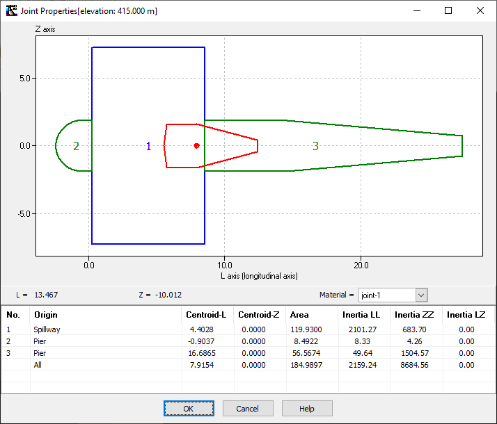
Figure 119
The user can, therefore, visualise all the components that make up the joint. In the case shown in Figure 119, a section at elevation 415 m crosses the chute, another crosses two sections of the pier. Each of these sections is listed and their geometric properties are displayed below the graphic representation. These properties are calculated using the corresponding mass center. In Figure 119, the component number is displayed at its center of mass. This window allows the modification of the material associated with the joint, through the drop-down list to the right of the Material label.
Any vertical load applied within the red area will result in compression over the analysis plane.