First method
The b-c-f triangle is used as an initial XY plane with point b as the origin. Entry data for inserting the origin of this plane are shown in Figure 104.
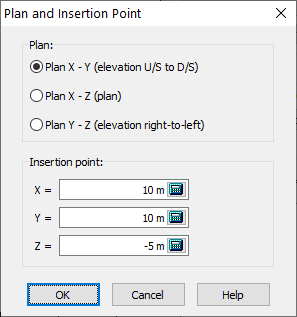
Figure 104
Figure 105 shows the section of the plane that has been defined using three linear segments. The description of the segments is also shown in the window.
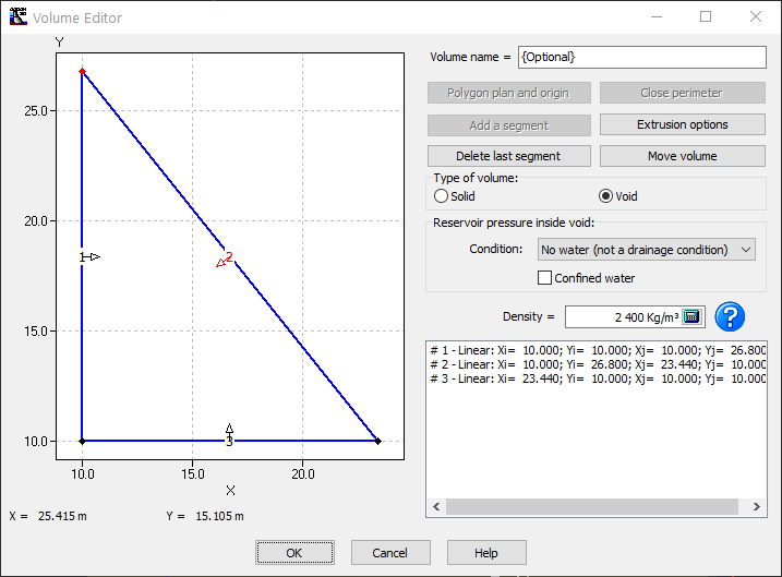
Figure 105
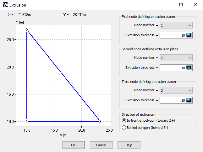
Figure 106
The extrusion plane will be the plan (a-d-e) (Figure 103). Equal extrusions (20m) for the three nodes allow this plane to be defined. The extrusion option In front of polygon must be used to create the void shown in Figure 103. The In front of polygon option corresponds to the positive Z-axis since the working plane is X-Y in Figure 106.