Pseudo-dynamic method: Bouaanani and Miquel’s method
Basic assumptions – dynamic amplification
This method is based on the simplified response spectrum method as described by Miquel and Bouaanani (2010). The user should consult this reference for a full description of the input variables to CADAM3D. A pseudo-dynamic seismic analysis is based on the response spectrum method. It is conceptually similar to a pseudo-static analysis, except that it recognizes the dynamic amplification of the inertia forces over the height of the dam. However, the oscillatory nature of forces is not considered..
Seismic accelerations
The pseudo-dynamic method does not consider the oscillatory nature of the seismic loads. It is therefore appropriate to perform safety assessment in two phases: (a) Maximum stress evaluation using spectral acceleration values, and (b) stability analysis using sustained spectral acceleration values (Figure 153). It is assumed that dynamic amplification applies only to horizontal accelerations. The vibration period of the dam in the vertical direction is considered small enough to neglect vertical seismic amplification along the height of the dam.
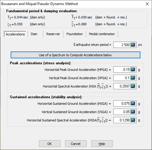
Figure 153
Most acceleration spectra are defined with a damping ratio of 5%. This damping ratio would likely be different when considering the combined dam-foundation-reservoir system. A tool in CADAM3D is available to evaluate the adjusted spectrum corresponding to a damping ratio different from 5% by clicking Use of a Response Spectrum to Calculate accelerations below (Figure 153) which opens the window in Figure 154. The first step is to define the 5% damping spectrum by using Define your spectrum tool.
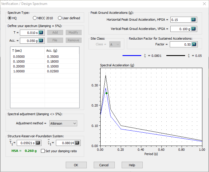
Figure 154
CADAM3D will then calculate the revised spectrum using the modified damping ratio computed for the dam-foundation-reservoir system (blue graph). This value is typed in green in Figure 154. The user can specify a specific damping ratio, different from CADAM3D, by clicking Modify damping.
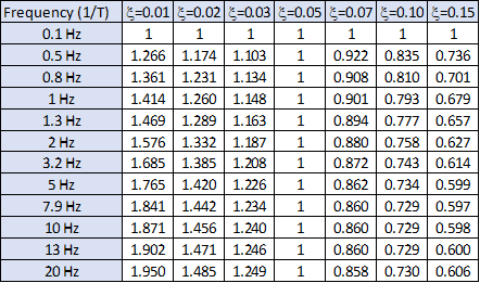
It should be noted that the Spectral adjustment drop-down list allows the user to choose between seven different methods to adjust spectra according to various damping ratios.
|
Adjustment method |
Adjustment factor |
|
Atkinson and Pierre (2004) |
|
|
AASHTO Koval-WNA* |
|
|
Chile CSA.S6-14 |
|
|
Eurocode 8 |
|
|
(Newmark-Hall) |
|
|
Koval–ENA* |
|


* WNA=Western North America; ENA=Eastern North America
The other types of response spectra that can be used are HQ (Newmark Hall) and NBCC 2010 (only available in a special proprietary version of CADAM3D).
Dam Properties
To ensure the accuracy of Bouaanani and Miquel's pseudo-dynamic method, the structure must be divided into layers to perform the numerical integration. The user can specify a number of divisions, ranging from 11 to 301. The dynamic flexibility of the dam is modeled with the dynamic elastic modulus of concrete (Es). The damping ratio of the dam resting on a rigid foundation without reservoir interaction is necessary to calculate the damping ratio of the dam-foundation-reservoir system (![]() ).
).
Any change to the fundamental parameters will immediately affect the fundamental vibration period as well as the damping ratio of the dam-reservoir-foundation system evaluated in the dialogue box (Figure 155) This allows the user to assess immediately the spectral accelerations values.
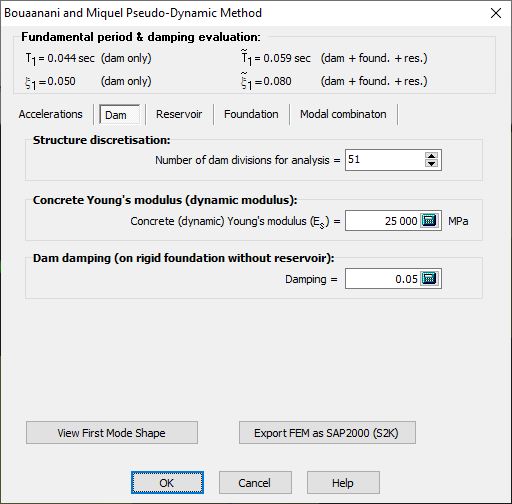
Figure 155
Unlike Chopra’s method, the Bouaanani and Miquel’s method (2010) uses beam theory with the Finite Element Method (FEM) to assess the fundamental vibration mode of the structure without interaction with the reservoir and the foundation.
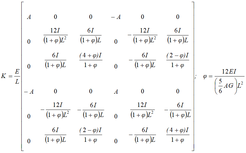
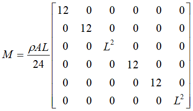
CADAM3D models the dam using beam elements with three degrees of freedom at each node (horizontal and vertical translation and rotation). Axial (EA), bending (EI) and shear (5/6 AG) rigidities are calculated for each element stiffness [K,] according to Timoshenko's formulation (Ghali 1989). Translational masses and rotational inertias are considered in a diagonal mass matrix [M].
The inverse iteration method is used to calculate the first vibration mode taking into account the magnitude and spatial distribution of masses and rigidities. This formulation allows a better estimate of the fundamental vibration mode when geometry or mass distribution does not correspond to Chopra's assumptions. Figure 156 presents the first normalised mode shape (with an effective modal mass =1) calculated by CADAM3D using the FEM. This window can be accessed by clicking View First Mode Shape in Figure 155.
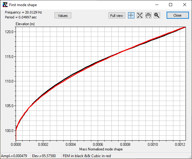
Figure 156
The red line in Figure 156 corresponds to the cubic function used in CADAM3D for modeling the fundamental mode while the black line corresponds to the fundamental mode estimated by the FEM. It is recommended that the user ensures the cubic function correctly matches the FEM. To modify these mode shapes, the number of divisions can be varied, as shown in Figure 155. The Values button allows the user to access the modal values, as shown in Figure 156.
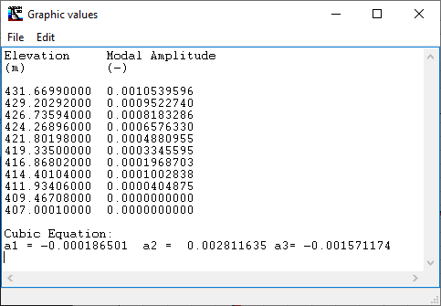
Figure 157
Reservoir Properties
Bouaanani and Miquel’s method allows considering water compressibility if desired. This parameter influences hydrodynamic loads in particular and it is recommended to consider compressibility (default value). More details are available from Miquel and Bouaanani (2010).
The velocity of pressure waves in water is actually the speed of sound in the water. In general, it is assumed to be at 1440 m/sec (4720 ft/sec).
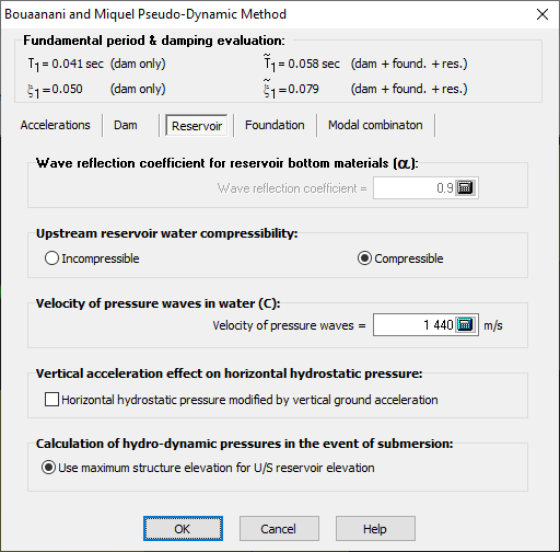
Figure 158
Foundation Properties
The interaction of the dam with the rock foundation changes the fundamental vibration period as well as the damping ratio of the dam-foundation-reservoir system. The hysteretic damping of the foundation (ηf) has an impact on the damping ratio of the dam-reservoir-foundation system (Figure 159).
Bouaanani and Miquel’s method (2010) does not consider foundation flexibility. CADAM3D, therefore, uses the same formulations as in Chopra’s method (1988) to calculate the increase in period as well as the additional damping caused by the flexibility of the bedrock.
![]()
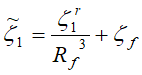
![]() = fundamental period of the dam-reservoir system;
= fundamental period of the dam-reservoir system;
Rf = Increment factor according to Chopra’s method;
![]() = damping ratio for dam-reservoir system;
= damping ratio for dam-reservoir system;
![]() = foundation damping ratio.
= foundation damping ratio.
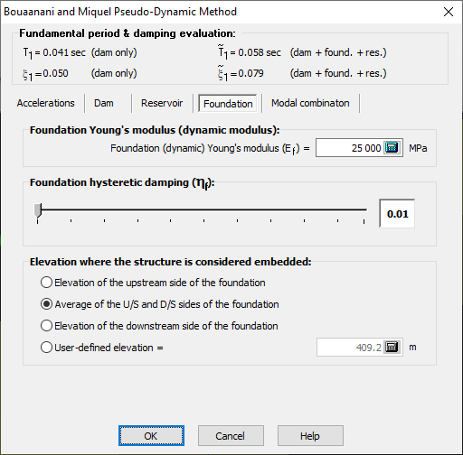
Figure 159
The Elevation where the structure is considered embedded refers to the elevation where the structure base is considered fixed, thus the modal displacement will be zero at this elevation and below. This elevation must be located within the minimum and the maximum elevations defined by the foundation profile. This parameter has a significant influence on the structure fundamental mode shape of vibration (see Figure 160). By default, CADAM3D use the average elevation of the upstream and the downstream sides of the foundation.
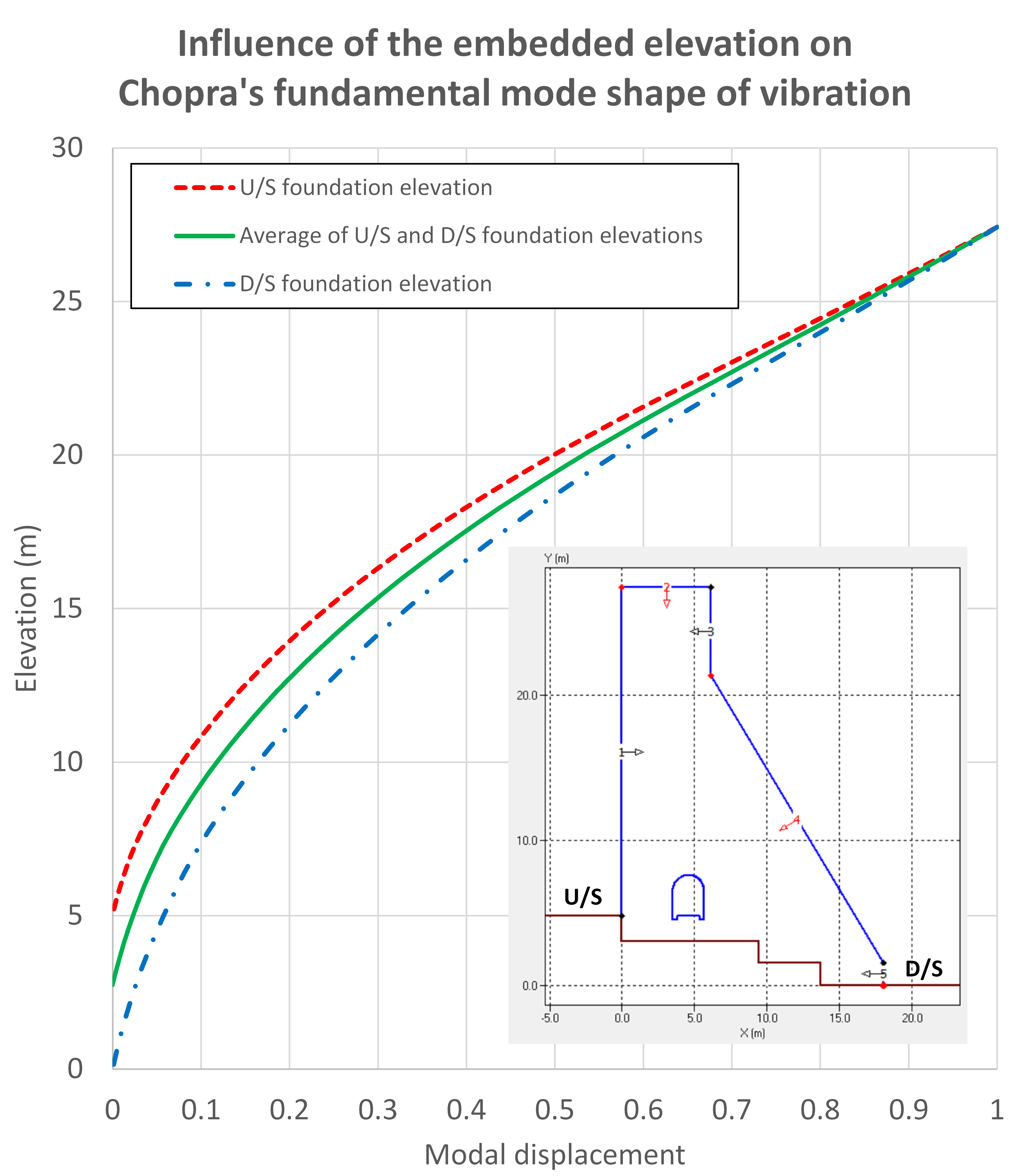
Figure 160
Modal combination
The maximum response of the fundamental and higher vibration modes of vibration do not occur at the same time. A modal combination must therefore be considered. Four options are available (Figure 161):
• Only the first vibration mode;
• Only the higher modes of vibration (static correction);
• SRSS (square root of the sum of the squares of the first and higher modes);
• Absolute sum of modes that yields conservative results.
SRSS is often considered the most appropriate option.
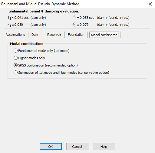
Figure 161