Pseudo-static method (seismic coefficient)
In a pseudo-static analysis, the earthquake seismic forces are calculated using the product of mass and acceleration according to d’Alembert’s principle.
Positive direction of inertia forces: According to d’Alembert principle, the inertia forces, induced by an earthquake are opposed to the direction of the base acceleration (Figure 9). A positive acceleration results in a negative inertia force.
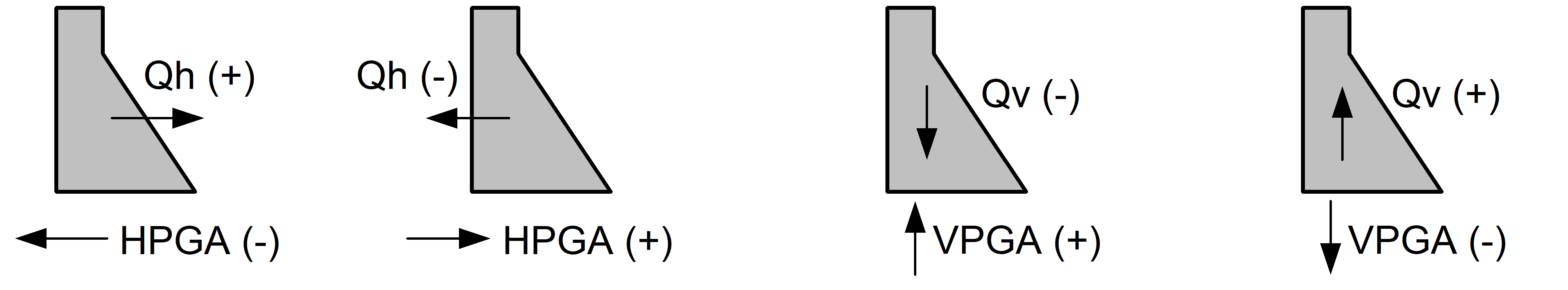
Figure 9
In a pseudo-static analysis, the dynamic amplification, due to the flexibility of the structure, is neglected. The dam-foundation-reservoir system is therefore considered a rigid system with a vibration period equal to zero.
Initial pre-earthquake condition
Any seismic analysis starts with a static analysis to determine the initial loading conditions of the structure. If cracking occurs during the initial static analysis, the crack length and corresponding uplift pressures are updated and the calculation is repeated until the tip of the crack reaches either zero stress or the tensile strength. After determining the initial conditions, the inertia loads caused by the earthquake can be applied.
Seismic accelerations
The Seismic coefficient button allows the definition of the rock acceleration and the specification of parameters for hydrodynamic and hydrostatic pressures. The peak and sustained accelerations must be defined. The seismic analysis is carried out in two successive phases: stress analysis followed by stability analysis.
Stress and stability analysis: The objective of a stress analysis is to determine crack lengths in joints when the structure is subjected to seismic loads (Figure 139). In this initial analysis, the peak ground acceleration is considered. This approach assumes that a peak acceleration can induce cracking in the dam. However, because the peak acceleration is of short duration, there is not enough time for a significant displacement to occur along the cracked plane. If there are no significant displacements, the dynamic stability of the structure is maintained. However, if cohesion has been specified for a particular joint, it may likely be removed during opening-closing cycles in a seismic event. The stress analysis, therefore, determines the cracked lengths that will be applied in the stability analysis.
The objective of the stability analysis is to determine the behaviour of the structure vis-à-vis the sliding and overturning reversing mechanisms. The pseudo-static method does not recognize the oscillatory nature of seismic loads. It is generally accepted that stability calculations can, therefore, be performed using a sustained acceleration ranging from 0.67 to 0.5 times the peak acceleration. In this case, sliding safety factors are calculated by considering the crack lengths obtained from the stress analysis (USACE 2007, Tinawi et al. 2000).
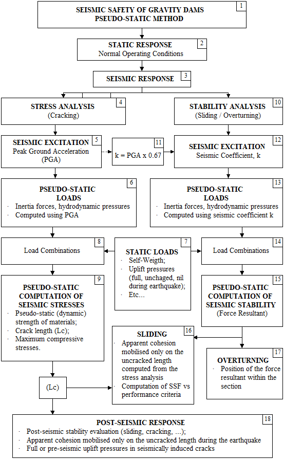
Figure 139
It is recommended to evaluate the seismic safety of a structure using a progressively complex approach: (a) the pseudo-static method, (b) the pseudo-dynamic method and (c) transient dynamic methods. It is important to note that equal values can be specified for the sustained and peak accelerations if the user so desires.
Peak and sustained accelerations
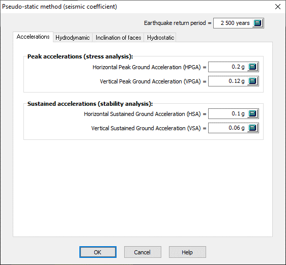
Figure 140
Earthquake return period: This value is not considered in the calculations. It is simply reported in the results sheets as additional information.
Peak acceleration (stress analysis): The peak acceleration values for stress analysis are specified as shown in Figure 140.
Sustained accelerations (stability analysis): The sustained accelerations for stability analysis are specified as shown in Figure 140.
Acceleration directions: The seismic stability analysis of a dam can be verified using upstream or downstream accelerations. Similarly, vertical acceleration can be oriented up or down. Cracking can be initiated and propagated from either upstream or downstream face. Existing cracks, obtained from the initial static conditions, may close depending on the intensity and orientation of the seismic forces.
Hydrodynamic pressure (Westergaard added masses)
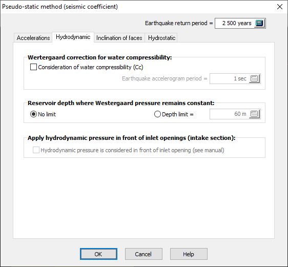
Figure 141A
The hydrodynamic pressure acting on the dam is modeled as added masses using Westergaard's formulation. Options are provided to:
Correction for water compressibility: Depending on the predominant period of ground acceleration, a correction factor is applied to the Westergaard formulation (USACE 1995, Corns et al. 1988).
Depth at which hydrodynamic pressures remain constant: This option allows the investigation of various recommendations from dam safety guidelines. For example, beyond a depth of 60m, there is no longer any significant variation in hydrodynamic pressure with depth. The value calculated at a depth of 60m is kept constant from this point down to the heel of the dam.
Apply hydrodynamic pressure in front of inlet opening (intake section): The hydrodynamic pressure profile can be disrupted by the upstream openings. The user has the option to maintain the pressure profile unchanged irrespective of the openings (Figure 141B). By activating this option (circled in red Figure 141B), the user considers that Westergaard's full hydrodynamic pressure should apply to both the upstream concrete face and at the entrance to hydraulic passages. This option remains conservative.
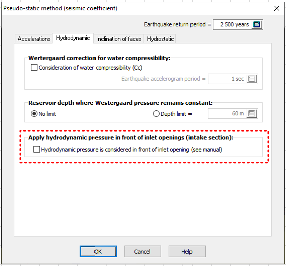
Figure 141B
Upstream and downstream face inclination
Hydrodynamic pressures act in the normal direction to the accelerated surface towards the reservoir.
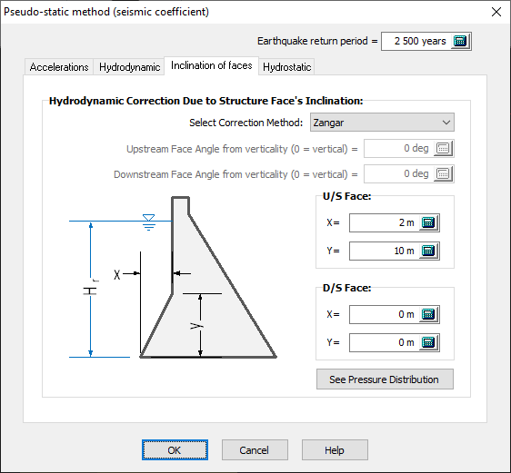
Figure 142
To transform these pressures to the global coordinate system, CADAM3D calculates hydrodynamic pressures using five possible methods:
1. No correction (no pressure reduction)
2. Westergaard generalized (see Westergaard Generalized Formulation 3D)
3. cos2 (see Cos² and Corns et al (1988) formulation for inclined faces)
4. Corn's et al. (see Cos² and Corns et al (1988) formulation for inclined faces)
5. Zangar (see Zangar (1952) formulation for inclined faces)
Modification of hydrostatic pressure due to vertical acceleration
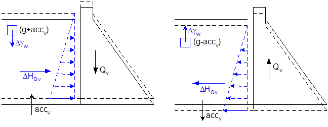
Vertical accelerations can reduce or amplify the gravtitational acceleration acting on the water mass density and thus affect the value of hydrostatic pressure acting on the walls of the structure. By default, hydrodynamic pressures are not affected by vertical accelerations. However, the user can activate this option by checking the appropriate box (Figure 143).
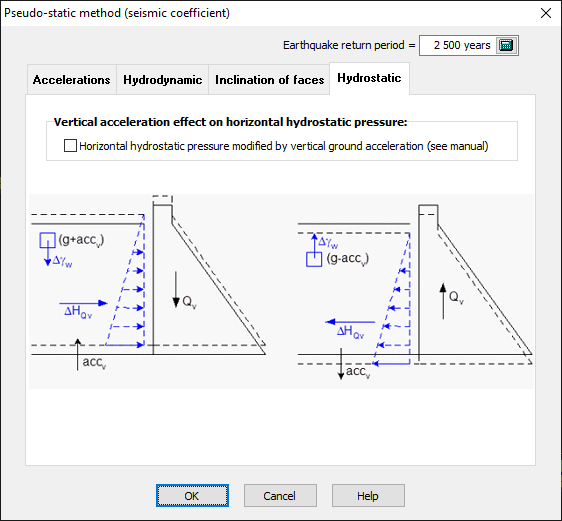
Figure 143
In addition to the vertical motion of the u/s face of the dam, some analysts consider the effect of the vertical acceleration of the reservoir bottom on the applied hydrostatic pressures. According to d’Alembert principle, an upward vertical acceleration of the rock is going to produce an increase in the effective volumetric weight of water (γe = ρw (g + accv)) for an incompressible reservoir, where ρw is the volumetric mass of water and g is the acceleration of gravity. The increase in the volumetric weight of water produces an increase in the initially applied hydrostatic pressures on the submerged parts of the dam. In reverse, rock acceleration directed downward produces a reduction in the effective volumetric weight of water (γe = ρw (g ‑ accv)) and related initial hydrostatic pressures. These considerations are independent of the Westergaard hydrodynamic pressure computations.