Modeling
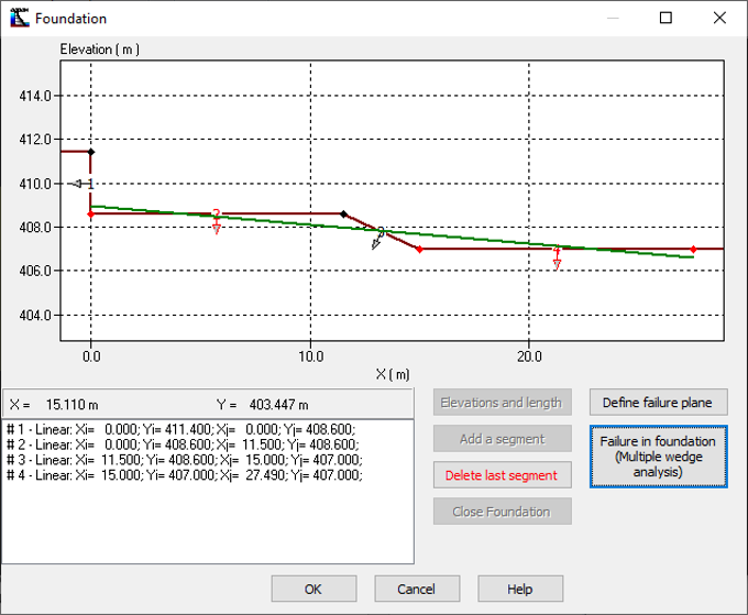
Figure24
To model the failure planes in the foundation, the user must access the Foundation dialogue window. Once the foundation profile is completed, the user can set the parameters for the multiple-wedge analysis by clicking the Failure in foundation button (Figure 24).
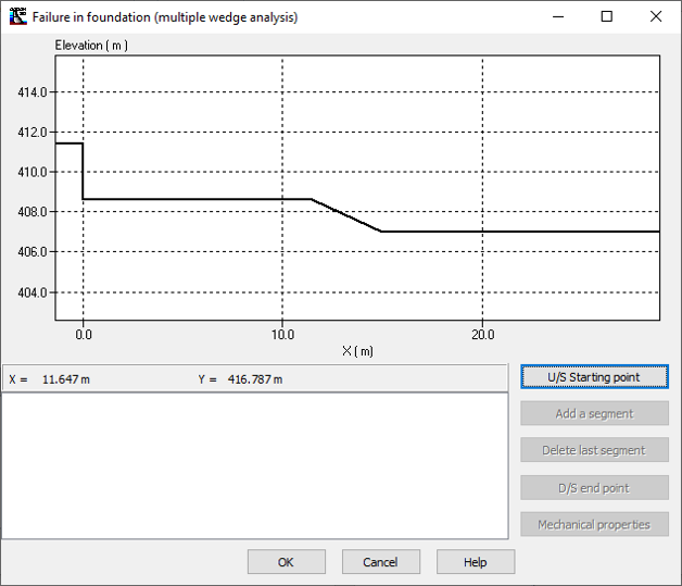
Figure 25
Similarly, for any other segment modeling, the user must proceed from upstream to downstream. To start, it is necessary to define the initial wedge U/S starting point of the failure profile (Figure 26) which must be at the base of the reservoir (negative X coordinate). The initial point is identified by a red dot in Figure 27.
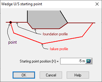
Figure 26
Then, the user can introduce as many segments as required to define the failure profile within the foundation. The types of segments available are the linear segment, the arc, the power and the polynomial equation. These four types of segments are described in detail in section Modeling by segments.
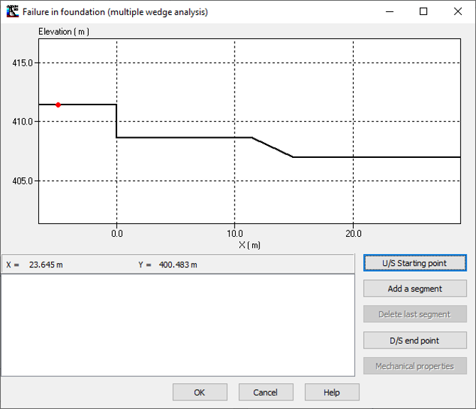
Figure 27
Figure 27 illustrates the addition of a linear segment. The user can also define segments that run along the foundation profile, to model cracks that intercept the base of the structure.
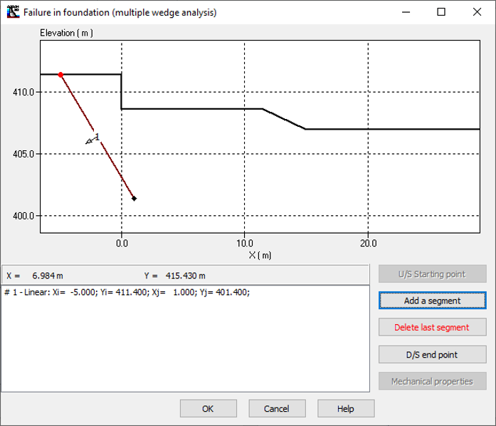
Figure 28
To close the failure planes on the downstream profile of the foundation, the X coordinate of the final or arrival point must be specified. This value (X) must be higher or equal to the downstream foot of the structure.
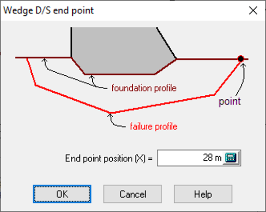
Figure 29
Figure 30 shows 3 linear failure planes. The first two planes were modeled by adding linear segments while the last linear segment is defined by the addition of the downstream final point to the last point of the second segment.
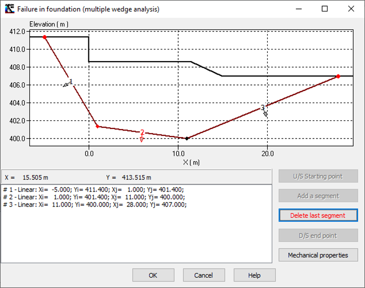
Figure 30