Material Definition and general parameters
A concrete lift joint is a concrete-concrete interface located above the rock-concrete contact (or base joint). To consider lift joints as well as the rock-concrete contact in a CADAM3D analysis, the mechanical properties of these interfaces and their locations must be defined.
The material properties can be defined using the Materials window. The concrete-concrete and rock-concrete planes use the same Mohr-Coulomb model. By default, the material at the rock-concrete contact is named Base (see Figure 113). Using the Add button, the user can create as many materials as required to define mechanical behaviour at the various lift joints (analysis planes in the structure).
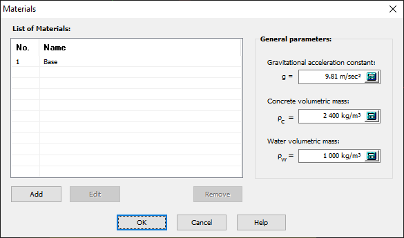
Figure 113
The user must provide the following mechanical properties:
- Compressive strength (f'c): used only to check performance criteria. Normal stresses, in hydraulic structures, are generally much lower than the compressive strength. For this reason, CADAM3D does not consider damage due to compression.
- Tensile strength (ft): used to calculate cracking in analysis planes (concrete-concrete and rock-concrete contacts). Note this value can be modified upon crack initiation or crack propagation (see section Modification to the tensile strength )
- Peak or residual cohesion (c): used to evaluate the sliding safety factor. The cohesion is the shear strength resistance at zero normal stress.
- Peak or residual friction angle (ϕ): used to calculate the sliding safety factors. The friction angle is given in degrees and the corresponding shear resistance is calculated using:
 ; σ = normal stress
- Minimum peak or residual compressive stress (σn): Refer to next section for more details (Minimum compressive stress to mobilize cohesion).
- Mohr-Coulomb Model (Options 1, 2 or 3): Refer to next section (Minimum compressive stress to mobilize cohesion).
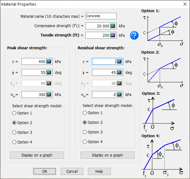
Figure 114
Minimum compressive stress (σn) to mobilise cohesion
The apparent cohesion, Ca, is sometimes used to define a rough non-cohesive joint with surface asperities having zero tensile resistance. Apparent cohesion is generally defined by the intersection, with the vertical shear axis, of a linear regression line obtained from shear tests conducted at different normal stress levels (Figure 115). This value, therefore, corresponds to the shear resistance under zero normal stress. However, because the joint is non-cohesive, by definition, the shear resistance of the interface must be zero under zero normal stress. Thus, a minimum compressive stress value can be specified for mobilizing an apparent cohesion along a non-cohesive joint. For normal stress intensities below the minimum value (σn*), two options are available:
Option 1: The shear resistance is equal to the compressive stress multiplied by the friction coefficient tanϕ. The real or apparent cohesion is used if σn ≥ σn*.
Option 2: The shear resistance is equal to the compression stress multiplied by the friction coefficient tan(ϕ+i). There is no cohesion when σn < σn*, but a larger friction coefficient σn < σn* is then used. For a compressive stress σn ≥ σn*, the friction angle ϕ is used with a cohesion Ca.
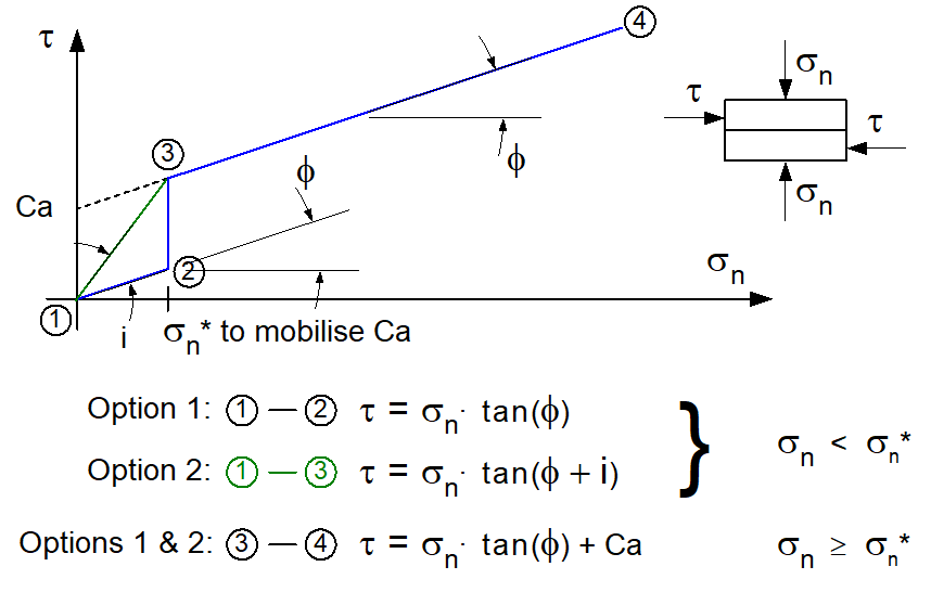
Figure 115
Please note that Options 1 and 2 will lead to the same results when σn* = 0 or Ca = 0, resulting in the usual Mohr-Coulomb failure envelope.
The third option allows the shear resistance to be considered in the uncracked tension zone (σn ≤ ft). Note that this option is non-conservative and few dam safety guidelines allow it.
Option 3: In the tension region, the shear resistance is equal to the tensile stress multiplied by the friction coefficient tan(j). In the compression region, the shear resistance is equal to the compressive stress multiplied by the friction coefficient tanϕ to which the cohesion is added.
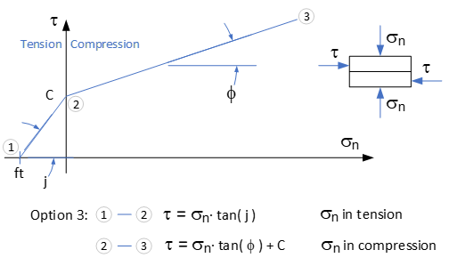
Figure 116
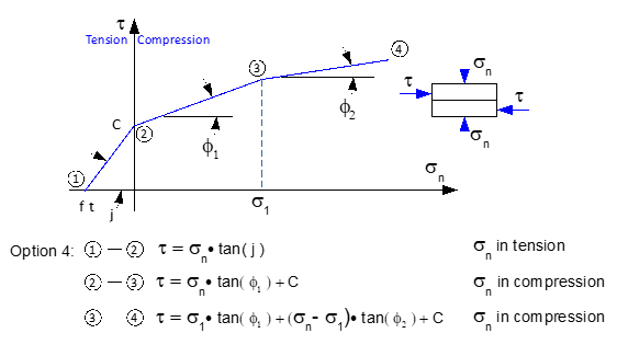
Option 4: In the tension region, the shear resistance is equal to the tensile stress multiplied by the friction coefficient tan(j). In the compression region, the shear resistance is governed by a bi-linear constitutive law as described below.