Generating hydraulic sections and penstock
Figure 60 presents the dialogue box for defining sections of hydraulic passages and penstock by clicking the Add section of the penstock dialogue box (Figure 57 below).
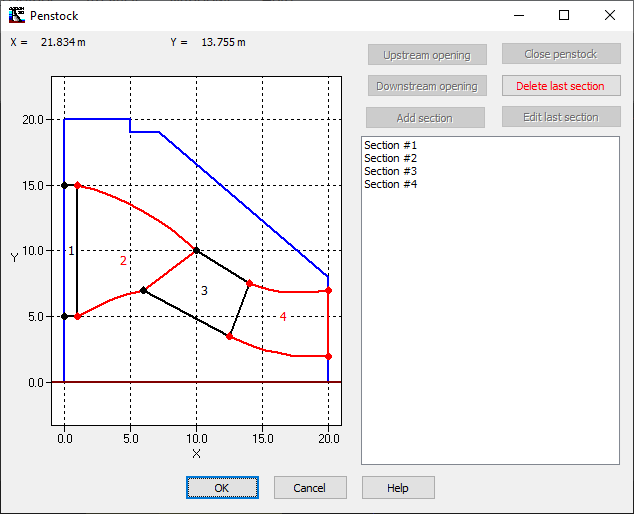
Figure 57
This dialogue box is divided into two sections: the definition of the top and bottom segments (X-Y plane) and the definition of the downstream end section in the perpendicular plane to the segments. The data in Figure 60 define a volume composed of two surfaces, represented by the U/S end section and the D/S end section which are linked by the upper and lower segments. The U/S end section is defined by the openings of the upstream face or by the D/S end section of the previous penstock section.
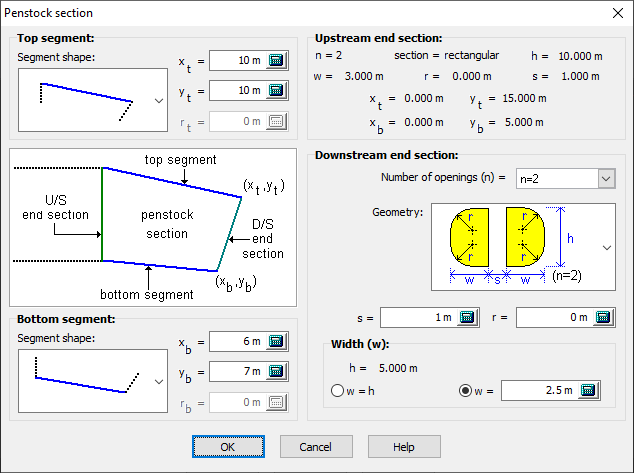
Figure 60
There are three different types of segments: the linear segment, the inner arc segment and the outer arc segment. The linear segment linearly connects the upstream point of the segment to the downstream point. The other two types of segments allow the link between two points by an arc, where the user specifies its radius. However, there are two possible configurations for drawing a circle through two points, as shown in Figure 61.
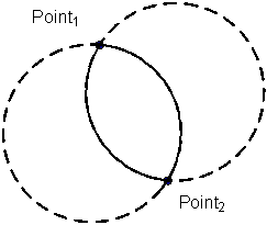
Figure 61
To allow the user to define the correct configuration of the arc, CADAM3D offers the following two possibilities (Figure 62):
- Outer arc radius: The arc radius is outside the penstock section or hydraulic passages;
- Inner arc radius: The arc radius is inside the penstock section or hydraulic passages.
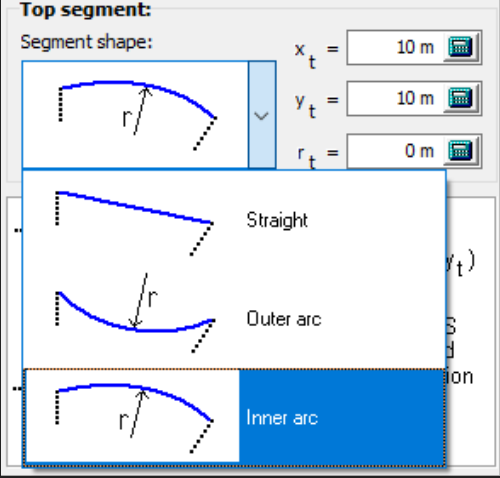
Figure 62
Once the first two segments are defined, it remains to define the section at the downstream end. The shape of the downstream section depends on the upstream section already defined. The details of the Upstream end section (Figure 63) are summarized in the upper right corner of the Penstock section dialogue box (Figure 60).
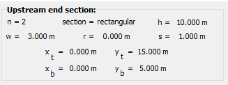
Figure 63
The numerous options and restrictions for defining the Downstream end section are handled by CADAM3D. They are not presented here.
Figure 64 shows part of the dialogue box in the penstock window that allows the definition of the downstream end. The user must specify the number of openings (n) that cannot exceed the number of openings at the upstream end. Then, a drop-down list determines the geometry based on the number of openings.
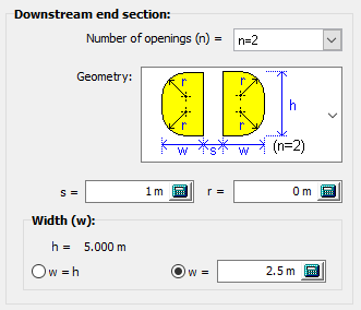
Figure 64
The various available geometries are shown in Figure 65.
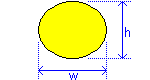
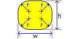
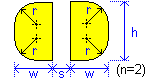
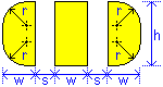
Figure 65
The width of each hydraulic passage or penstock is defined by the variable "w." The user can define the width of the piers, between hydraulic passages, with the variable "s". The radius "r" allows the rounding of corners. Rounding is only possible if the downstream opening end of the penstock is not rectangular. Finally, the "h" value, corresponding to the height of the section, is automatically calculated by CADAM3D.