Example 2
Suppose a drainage gallery exists in the previous example. Figure 110 shows a 3D view of the dam with a void and a gallery. Unlike the void, the gallery is extruded over the entire thickness of the dam. In this example, the gallery and void intersect in the central part of the dam, where the void has been defined.
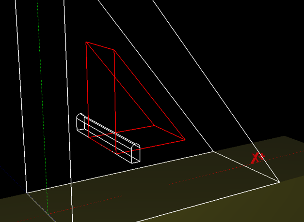
Figure 110
CADAM3D does not check the intersection between voids or user-defined volumes. If two of these elements are superimposed, volumes or voids at intersections are duplicated. It is the user's responsibility to check the geometry and set volumes or voids so that they do not intersect. In this example, the best solution is to add a volume equal to the void at the intersection. The mass and weight of the shared area are considered twice as a void and once as a solid volume resulting in a single void. This procedure is detailed in the following figures.
The cross-section plane of the element and the insertion point are defined first. The plane and the void insertion point defined in the previous example are defined again.
The 2D section of a solid volume is defined in the same way as the 2D section of a gallery using linear segments and one circular arc (Figure 111).
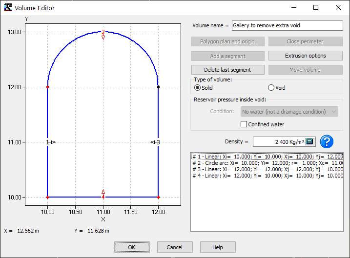
Figure 111
The extrusion plane used in the first method of example 1 is considered again. The final 3D view of the structure is shown in Figure 112. The volume added to compensate for intersecting voids is clearly shown.
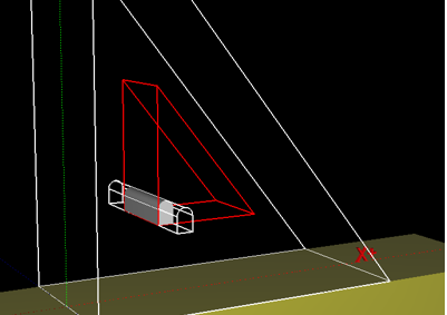
Figure 112